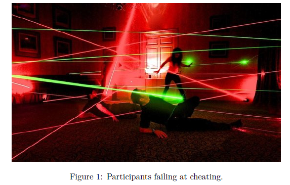
Lately William started going out clubbing and, as a result, he became very interested in lasers and laser-related systems. This new expertise came in handy, now that some of the IOIT participant teams started harassing him and Giorgio trying to extort hints about the tasks!
William is now building an Intrusion Detection System (IDS) to ensure that nobody can access their hotel room and steal classified information about the tasks.

William and Giorgio’s hotel room is meters long and meters wide. We can represent it as a grid where each cell might contain a laser connector (which is both emitter and receiver).
In order for two connectors to “see” each other (and shoot lasers at each other) they must be lined up either horizontally or vertically: our lasers can’t go diagonally. Two connectors can’t see each other if there are other connectors “blocking the view”; the light beams, however, can intersect.
William has just designed a graph on the whiteboard, consisting of vertices and edges. He would like to introduce a laser connector on the grid for every vertex in the graph, and a laser beam (between two connectors) for every edge in the graph. We will call this a laser arrangement of the graph.
It’s always possible to find a complete laser arrangement (where all vertices and edges are used) for the graph designed by William. However, he will be happy enough with a partial arrangement: something is better than nothing, to stop those mischievous participants!
Input data
The first line contains integers and . The second line contains integers and . The following lines contain two integers each: and , both of them between and , which represent a direct (and bidirectional) laser connection between vertex and vertex .
Output data
You need to write the board you produced, that is: lines with integers each. The -th integer of the -th line will be either:
- A dot character
.if the respective cell in the board is left empty. - Some non-negative integer , if you decide to put vertex in that cell.
Note that in a partial laser arrangement you don’t need to put all vertices in the grid: some may be ignored. That is: if you only print dots, it’s still a valid partial arrangement!
Moreover: if you want, you can put more spaces between cells for alignment purposes and they will be ignored. In the examples section we sometimes use two spaces instead of one.
Constraints and clarifications
- .
- .
- for each .
- There are no self loops () and no duplicate edges.
- The graph may not be connected.
Your program will be tested against several test cases grouped in subtasks. The score in each subtask will be calculated as the minimum score obtained in any of its test cases, multiplied by the value of the subtask. The score in a test case will be calculated as: , where is the difference between the number of connections established by your solution and .
| # | Score | Constraints |
|---|---|---|
| 1 | 5 | Examples |
| 2 | 15 | |
| 3 | 20 | , |
| 4 | 20 | |
| 5 | 20 | |
| 6 | 20 | No additional limitations. |
Example 1
stdin
2 3
4 4
0 1
2 3
2 1
0 3
stdout
0 3 .
1 2 .
Explanation
In the first sample case the presented solution is optimal.
Example 2
stdin
4 4
11 10
1 4
0 1
7 2
8 6
6 10
5 7
4 2
3 10
10 9
6 0
stdout
1 0 7 5
4 . 2 .
8 6 10 9
. . 3 .
Explanation
In the second sample case the presented solution is optimal.
Example 3
stdin
4 4
11 10
1 4
0 1
7 2
8 6
6 10
5 7
4 2
3 10
10 9
6 0
stdout
1 0 7 5
4 . 2 .
6 . 10 .
. . 3 9
Explanation
In the third sample case the presented solution establishes laser connections out of , thus scoring: out of a maximum of point.